



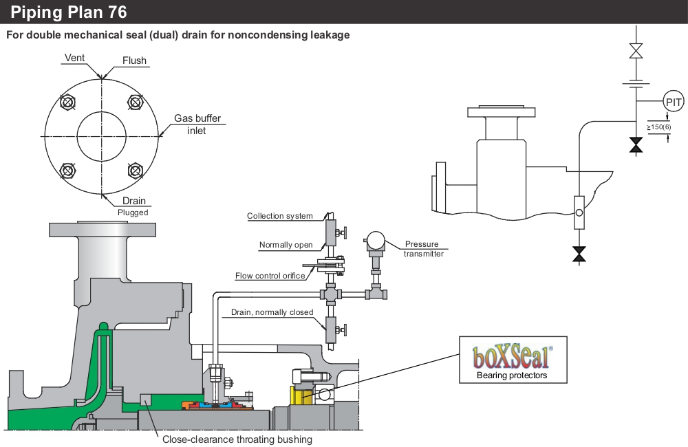
In Piping Plan 76 there is a containment seal chamber drain for noncondensing leakage on Arrangement 2 seals. This plan is used if the pumped fluid does not condense at ambient temperatures. This system is supplied by the vendor.
Tubing shall be 13 mm (1/2 in.) minimum diameter and shall rise continuously upward from the CSV connection to the piping/instrumentation harness.
The harness shall be pipe of minimum size DN 15 (NPS 1/2). Harness shall be supported from overhead structure or side stand such that no strain is put on the tubing connection to the seal gland plate.
Piping Plan 76 systems are typically used on Arrangement 2, unpressurized dual seals, which also utilize a dry containment seal and where leakage from the inner seal will not condense. They may be used with a buffer gas (Piping Plan 72) or without a buffer gas (Piping Plan 71).
If an unpressurized dual seal is installed, usually it is because leakage of the pumped fluid to the atmosphere should be restricted more than can be achieved with an Arrangement 1 seal. Therefore, a means is needed to route the leakage to a collection point. The Piping Plan 76 system is intended for services where no condensation of the inner seal leakage or from the collection system will occur. Should liquid accumulate in the containment seal chamber, excessive heat could be generated, leading to hydrocarbon coking and possible seal failure.
Piping Plan 76 is intended to work as follows: leakage from the inner seal is restricted from escape by the containment seal and goes out the containment-seal vent. An orifice in the outlet line of the collector restricts flow such that high leakage of the inner seal will cause a pressure increase and trigger the pressure transmitter to alarm at a gauge pressure of 0.07 MPa (0.7 bar) (10 psi). The block valve in the outlet serves to isolate the system for maintenance. It may also be used to test the inner seal by closing while the pump is in operation and noting the time/pressure buildup relationship in the collector. A drain connection on the piping harness may be used to inject nitrogen or other gas for the purpose of testing the containment seal as well as for checking for any liquid buildup.
The pressure transmitter in Piping Plan 76 will track the pressure in the vapor collection system. In normal operation, the pressure in the containment seal chamber can be as high as the vapor collection system pressure plus the check valve cracking pressure (if present). Pressures greater than this may indicate excessive leakage past the inner seal.